


When it comes to antennas, the question that people are most concerned about is "How is radiation actually achieved?" How does the electromagnetic field generated by the signal source propagate through the transmission line and inside the antenna, and finally "separate" from the antenna to form a free space wave.
1. Single wire radiation
Let us assume that the charge density, expressed as qv (Coulomb/m3), is uniformly distributed in a circular wire with a cross-sectional area of a and a volume of V, as shown in Figure 1.
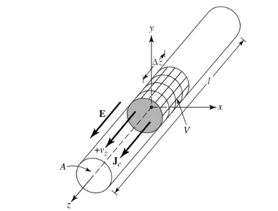
Figure 1
The total charge Q in volume V moves in the z direction at a uniform speed Vz (m/s). It can be proved that the current density Jz on the cross section of the wire is:
Jz = qv vz (1)
If the wire is made of an ideal conductor, the current density Js on the wire surface is:
Js = qs vz (2)
Where qs is the surface charge density. If the wire is very thin (ideally, the radius is 0), the current in the wire can be expressed as:
Iz = ql vz (3)
Where ql (coulomb/meter) is the charge per unit length.
We are mainly concerned with thin wires, and the conclusions apply to the above three cases. If the current is time-varying, the derivative of formula (3) with respect to time is as follows:
(4)
az is the charge acceleration. If the wire length is l, (4) can be written as follows:
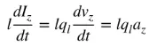
(5)
Equation (5) is the basic relationship between current and charge, and also the basic relationship of electromagnetic radiation. Simply put, to produce radiation, there must be a time-varying current or acceleration (or deceleration) of charge. We usually mention current in time-harmonic applications, and charge is most often mentioned in transient applications. In order to produce charge acceleration (or deceleration), the wire must be bent, folded, and discontinuous. When the charge oscillates in time-harmonic motion, it will also produce periodic charge acceleration (or deceleration) or time-varying current. Therefore:
1) If the charge does not move, there will be no current and no radiation.
2) If the charge moves at a constant speed:
a. If the wire is straight and infinite in length, there is no radiation.
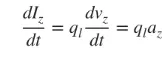
b. If the wire is bent, folded, or discontinuous, as shown in Figure 2, there is radiation.
3) If the charge oscillates over time, the charge will radiate even if the wire is straight.
Figure 2
A qualitative understanding of the radiation mechanism can be obtained by looking at a pulsed source connected to an open wire that can be grounded through a load at its open end, as shown in Figure 2(d). When the wire is initially energized, the charges (free electrons) in the wire are set in motion by the electric field lines generated by the source. As the charges are accelerated at the source end of the wire and decelerated (negative acceleration relative to the original motion) when reflected at its end, a radiation field is generated at its ends and along the rest of the wire. The acceleration of the charges is accomplished by an external source of force that sets the charges in motion and produces the associated radiation field. The deceleration of the charges at the ends of the wire is accomplished by internal forces associated with the induced field, which is caused by the accumulation of concentrated charges at the ends of the wire. The internal forces gain energy from the accumulation of charge as its velocity decreases to zero at the ends of the wire. Therefore, the acceleration of the charges due to the electric field excitation and the deceleration of the charges due to the discontinuity or smooth curve of the wire impedance are the mechanisms for the generation of electromagnetic radiation. Although both current density (Jc) and charge density (qv) are source terms in Maxwell's equations, charge is considered to be a more fundamental quantity, especially for transient fields. Although this explanation of radiation is mainly used for transient states, it can also be used to explain steady-state radiation.
Recommend several excellent antenna products manufactured by RFMISO:
RM-TCR406.4
RM-BCA082-4(0.8-2GHz)
RM-SWA910-22(9-10GHz)
2. Two-wire radiation
Connect a voltage source to a two-conductor transmission line connected to an antenna, as shown in Figure 3(a). Applying voltage to the two-wire line generates an electric field between the conductors. The electric field lines act on the free electrons (easily separated from atoms) connected to each conductor and force them to move. The movement of charges generates current, which in turn generates a magnetic field.
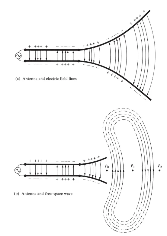
Figure 3
We have accepted that electric field lines start with positive charges and end with negative charges. Of course, they can also start with positive charges and end at infinity; or start at infinity and end with negative charges; or form closed loops that neither start nor end with any charges. Magnetic field lines always form closed loops around current-carrying conductors because there are no magnetic charges in physics. In some mathematical formulas, equivalent magnetic charges and magnetic currents are introduced to show the duality between solutions involving power and magnetic sources.
The electric field lines drawn between two conductors help to show the distribution of charge. If we assume that the voltage source is sinusoidal, we expect the electric field between the conductors to also be sinusoidal with a period equal to that of the source. The relative magnitude of the electric field strength is represented by the density of the electric field lines, and the arrows indicate the relative direction (positive or negative). The generation of time-varying electric and magnetic fields between the conductors forms an electromagnetic wave that propagates along the transmission line, as shown in Figure 3(a). The electromagnetic wave enters the antenna with the charge and the corresponding current. If we remove part of the antenna structure, as shown in Figure 3(b), a free-space wave can be formed by "connecting" the open ends of the electric field lines (shown by the dotted lines). The free-space wave is also periodic, but the constant-phase point P0 moves outward at the speed of light and travels a distance of λ/2 (to P1) in half a period of time. Near the antenna, the constant-phase point P0 moves faster than the speed of light and approaches the speed of light at points far from the antenna. Figure 4 shows the free-space electric field distribution of the λ∕2 antenna at t = 0, t/8, t/4, and 3T/8.
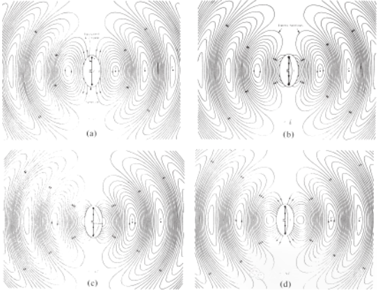
Figure 4 Free space electric field distribution of the λ∕2 antenna at t = 0, t/8, t/4 and 3T/8
It is not known how the guided waves are separated from the antenna and eventually formed to propagate in free space. We can compare guided and free space waves to water waves, which can be caused by a stone dropped in a calm body of water or in other ways. Once the disturbance in the water begins, water waves are generated and begin to propagate outward. Even if the disturbance stops, the waves do not stop but continue to propagate forward. If the disturbance persists, new waves are constantly generated, and the propagation of these waves lags behind the other waves.
The same is true for electromagnetic waves generated by electrical disturbances. If the initial electrical disturbance from the source is of short duration, the electromagnetic waves generated propagate inside the transmission line, then enter the antenna, and finally radiate as free space waves, even though the excitation is no longer present (just like the water waves and the disturbance they created). If the electrical disturbance is continuous, the electromagnetic waves exist continuously and follow closely behind them during propagation, as shown in the biconical antenna shown in Figure 5. When electromagnetic waves are inside transmission lines and antennas, their existence is related to the existence of electric charge inside the conductor. However, when the waves are radiated, they form a closed loop and there is no charge to maintain their existence. This leads us to the conclusion that:
Excitation of the field requires acceleration and deceleration of the charge, but maintenance of the field does not require acceleration and deceleration of the charge.
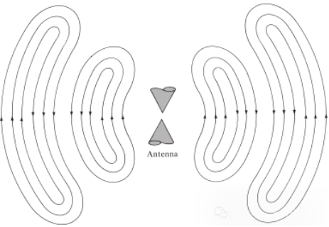
Figure 5
3. Dipole Radiation
We try to explain the mechanism by which the electric field lines break away from the antenna and form free-space waves, and take the dipole antenna as an example. Although it is a simplified explanation, it also enables people to intuitively see the generation of free-space waves. Figure 6(a) shows the electric field lines generated between the two arms of the dipole when the electric field lines move outward by λ∕4 in the first quarter of the cycle. For this example, let us assume that the number of electric field lines formed is 3. In the next quarter of the cycle, the original three electric field lines move another λ∕4 (a total of λ∕2 from the starting point), and the charge density on the conductor begins to decrease. It can be considered to be formed by the introduction of opposite charges, which cancel out the charges on the conductor at the end of the first half of the cycle. The electric field lines generated by the opposite charges are 3 and move a distance of λ∕4, which is represented by the dotted lines in Figure 6(b).
The final result is that there are three downward electric field lines in the first λ∕4 distance and the same number of upward electric field lines in the second λ∕4 distance. Since there is no net charge on the antenna, the electric field lines must be forced to separate from the conductor and combine together to form a closed loop. This is shown in Figure 6(c). In the second half, the same physical process is followed, but note that the direction is opposite. After that, the process is repeated and continues indefinitely, forming an electric field distribution similar to Figure 4.
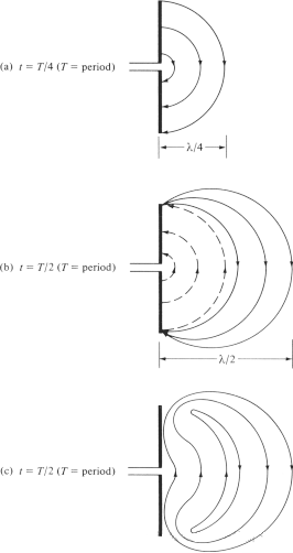
Figure 6
To learn more about antennas, please visit:
Post time: Jun-20-2024


