


Antenna efficiency describes how effectively accepted RF power is converted into radiated power. It is a key antenna parameter because conductor loss, dielectric loss and impedance mismatch can reduce usable radiation even when the antenna has a suitable pattern.
The basic radiation-efficiency formula is:
Radiation efficiency, erad = Prad / Paccepted
Total efficiency also includes mismatch at the antenna input:
Total efficiency, e0 = (1 - |Γ|2) erad
where Prad is radiated power, Paccepted is accepted power and Γ is the input reflection coefficient. This guide explains antenna efficiency formulas, loss mechanisms, gain, directivity, realized gain and common measurement methods.
Antenna Efficiency: Definitions and Formulas
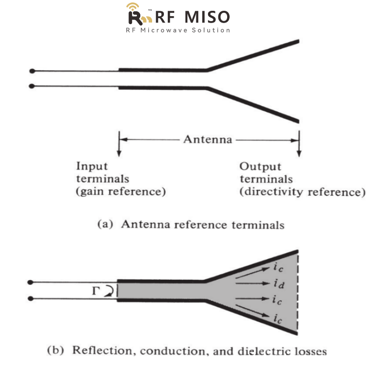
Figure 1
The concept of antenna efficiency can be defined using Figure 1.
The total antenna efficiency e0 is used to calculate the antenna losses at the input and within the antenna structure. Referring to Figure 1(b), these losses may be due to:
1. Reflections due to mismatch between the transmission line and the antenna;
2. Conductor and dielectric losses.
The total antenna efficiency can be obtained from the following formula:
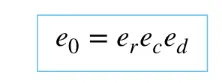
That is, total efficiency = product of mismatch efficiency, conductor efficiency and dielectric efficiency.
It is usually very difficult to calculate conductor efficiency and dielectric efficiency, but they can be determined by experiments. However, experiments cannot distinguish the two losses, so the above formula can be rewritten as:
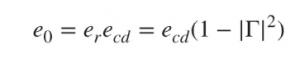
ecd is the radiation efficiency of the antenna and Γ is the reflection coefficient.
Gain, Directivity and Realized Gain
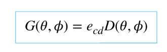
Directivity describes how concentrated the radiation pattern is in a given direction. Gain combines directivity with radiation efficiency:
G = eradD
where G is gain, D is directivity and erad is radiation efficiency. Gain therefore accounts for conductor and dielectric loss but normally excludes impedance-mismatch loss.

In general, it refers to relative gain, which is defined as "the ratio of the power gain in a specified direction to the power of a reference antenna in a reference direction". The input power to this antenna must be equal. The reference antenna can be a vibrator, horn or other antenna. In most cases, a non-directional point source is used as the reference antenna. Therefore:

The relationship between total radiated power and total input power is as follows:
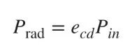
Realized gain includes the effect of input mismatch and is related to gain by:
Grealized = (1 - |Γ|2)G
When the antenna is well matched, realized gain approaches gain. If the mismatch is significant, realized gain is lower even when the radiation pattern and radiation efficiency remain unchanged.
The relationship between gain and directivity is:
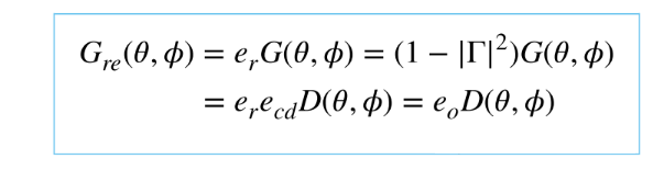
If the antenna is perfectly matched to the transmission line, |Γ| = 0 and realized gain equals gain. In practical systems, cable loss and the calibration reference plane must also be considered when comparing measured and simulated values.
Key Factors That Reduce Antenna Efficiency
- Finite conductor conductivity and surface roughness
- Dielectric loss in substrates, radomes and support materials
- Impedance mismatch at the feed
- Lossy matching networks, connectors and feed structures
- Installation near metal, absorbing materials or the human body
- Manufacturing tolerances and frequency-dependent current distribution
How Antenna Efficiency Is Measured
Measurement method depends on antenna type, frequency range and available test facilities. Common approaches include gain-directivity comparison, radiation-pattern integration, reverberation-chamber measurements and the Wheeler-cap method for suitable electrically small antennas. Accurate calibration, cable-loss correction, polarization alignment and a clearly defined reference plane are essential for meaningful results.
Using Efficiency and Gain in Antenna Selection
Efficiency, gain, realized gain, bandwidth, polarization, beamwidth and VSWR should be evaluated together. A high-directivity antenna can still deliver poor realized gain if loss or mismatch is excessive. Engineers should compare values across the full operating band and under representative mounting conditions.
Explore RF MISO antenna solutions or review our antenna testing capabilities. For application-specific selection, share the operating band, required gain, polarization, mounting constraints and test environment with the RF MISO team.
To learn more about antennas, please visit:

Post time: Jun-14-2024


