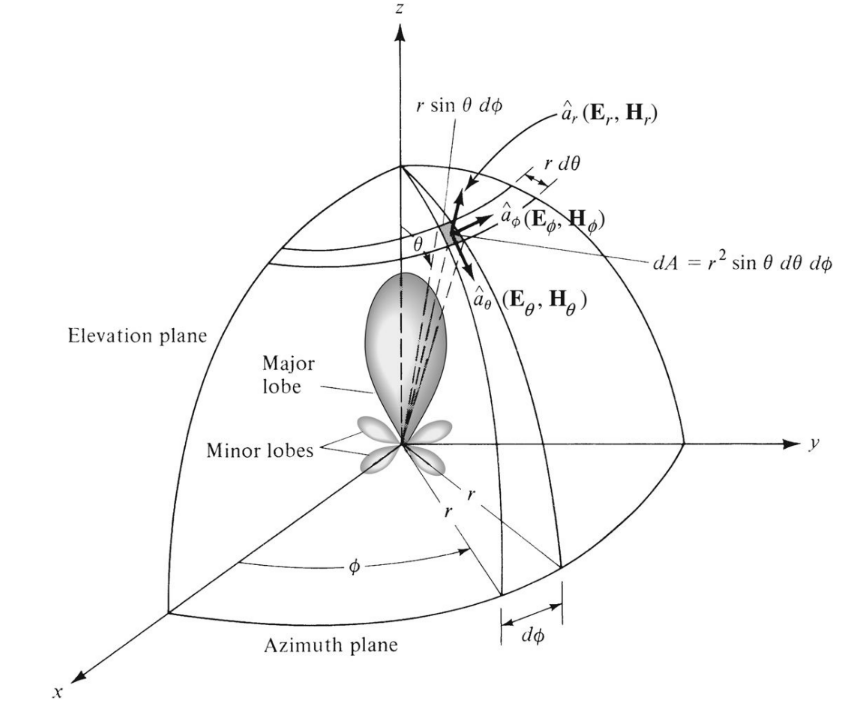
figure 1
1. Beam efficiency
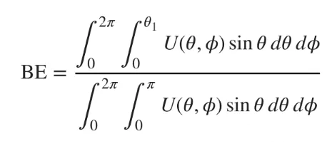
Another common parameter for evaluating the quality of transmitting and receiving antennas is beam efficiency. For the antenna with the main lobe in the z-axis direction as shown in Figure 1, beam efficiency (BE) is defined as:

It is the ratio of the power transmitted or received within the cone angle θ1 to the total power transmitted or received by the antenna. The above formula can be written as:

If the angle at which the first zero point or minimum value appears is selected as θ1, the beam efficiency represents the ratio of the power in the main lobe to the total power. In applications such as metrology, astronomy, and radar, the antenna needs to have a very high beam efficiency. Usually more than 90% is required, and the power received by the side lobe must be as small as possible.
2. Bandwidth
The bandwidth of an antenna is defined as "the frequency range over which the performance of certain characteristics of the antenna meets specific standards". The bandwidth can be considered as a frequency range on both sides of the center frequency (generally referring to the resonant frequency) where the antenna characteristics (such as input impedance, directional pattern, beamwidth, polarization, sidelobe level, gain, beam pointing, radiation efficiency) are within the acceptable range after comparing the value of the center frequency.
. For broadband antennas, the bandwidth is usually expressed as the ratio of the upper and lower frequencies for acceptable operation. For example, a bandwidth of 10:1 means that the upper frequency is 10 times the lower frequency.
. For narrowband antennas, the bandwidth is expressed as a percentage of the frequency difference to the center value. For example, a 5% bandwidth means that the acceptable frequency range is 5% of the center frequency.
Because the characteristics of the antenna (input impedance, directional pattern, gain, polarization, etc.) vary with frequency, the bandwidth characteristics are not unique. Usually the changes in the directional pattern and input impedance are different. Therefore, the directional pattern bandwidth and impedance bandwidth are needed to emphasize this distinction. The directional pattern bandwidth is related to the gain, sidelobe level, beamwidth, polarization and beam direction, while the input impedance and radiation efficiency are related to the impedance bandwidth. Bandwidth is usually stated in terms of beamwidth, sidelobe levels, and pattern characteristics.
The above discussion assumes that the dimensions of the coupling network (transformer, counterpoise, etc.) and/or antenna do not change in any way as the frequency changes. If the critical dimensions of the antenna and/or the coupling network can be properly adjusted as the frequency changes, the bandwidth of a narrowband antenna can be increased. While this is not an easy task in general, there are applications where it is achievable. The most common example is the radio antenna in a car radio, which usually has an adjustable length that can be used to tune the antenna for better reception.
To learn more about antennas, please visit:
Post time: Jul-12-2024


