


1. Introduction to Antennas
An antenna is a transition structure between free space and a transmission line, as shown in Figure 1. The transmission line can be in the form of a coaxial line or a hollow tube (waveguide), which is used to transmit electromagnetic energy from a source to an antenna, or from an antenna to a receiver. The former is a transmitting antenna, and the latter is a receiving antenna.
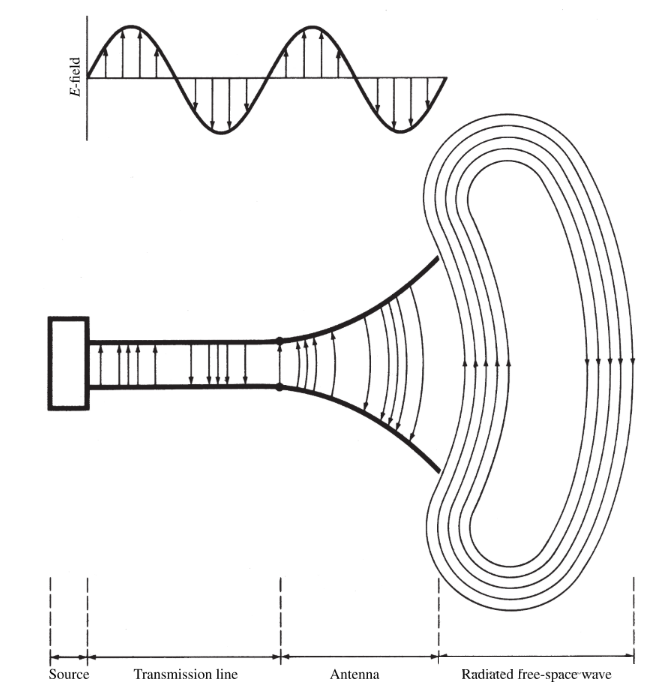
Figure 1 Electromagnetic energy transmission path (source-transmission line-antenna-free space)
The transmission of the antenna system in the transmission mode of Figure 1 is represented by the Thevenin equivalent as shown in Figure 2, where the source is represented by an ideal signal generator, the transmission line is represented by a line with characteristic impedance Zc, and the antenna is represented by a load ZA [ZA = (RL + Rr) + jXA]. The load resistance RL represents the conduction and dielectric losses associated with the antenna structure, while Rr represents the radiation resistance of the antenna, and the reactance XA is used to represent the imaginary part of the impedance associated with the antenna radiation. Under ideal conditions, all the energy generated by the signal source should be transferred to the radiation resistance Rr, which is used to represent the radiation capability of the antenna. However, in practical applications, there are conductor-dielectric losses due to the characteristics of the transmission line and the antenna, as well as losses caused by reflection (mismatch) between the transmission line and the antenna. Considering the internal impedance of the source and ignoring the transmission line and reflection (mismatch) losses, the maximum power is provided to the antenna under conjugate matching.
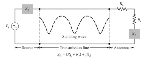
Figure 2
Because of the mismatch between the transmission line and the antenna, the reflected wave from the interface is superimposed with the incident wave from the source to the antenna to form a standing wave, which represents energy concentration and storage and is a typical resonant device. A typical standing wave pattern is shown by the dotted line in Figure 2. If the antenna system is not designed properly, the transmission line can act as an energy storage element to a large extent, rather than as a waveguide and energy transmission device.
The losses caused by the transmission line, antenna and standing waves are undesirable. Line losses can be minimized by selecting low-loss transmission lines, while antenna losses can be reduced by reducing the loss resistance represented by RL in Figure 2. Standing waves can be reduced and energy storage in the line can be minimized by matching the impedance of the antenna (load) with the characteristic impedance of the line.
In wireless systems, in addition to receiving or transmitting energy, antennas are usually required to enhance radiated energy in certain directions and suppress radiated energy in other directions. Therefore, in addition to detection devices, antennas must also be used as directional devices. Antennas can be in various forms to meet specific needs. It may be a wire, an aperture, a patch, an element assembly (array), a reflector, a lens, etc.
In wireless communication systems, antennas are one of the most critical components. Good antenna design can reduce system requirements and improve overall system performance. A classic example is television, where broadcast reception can be improved by using high-performance antennas. Antennas are to communication systems what eyes are to humans.
2. Antenna Classification
1. Wire Antenna
Wire antennas are one of the most common types of antennas because they are found almost everywhere - cars, buildings, ships, airplanes, spacecraft, etc. There are various shapes of wire antennas, such as straight line (dipole), loop, spiral, as shown in Figure 3. Loop antennas do not only need to be circular. They can be rectangular, square, oval or any other shape. The circular antenna is the most common because of its simple structure.
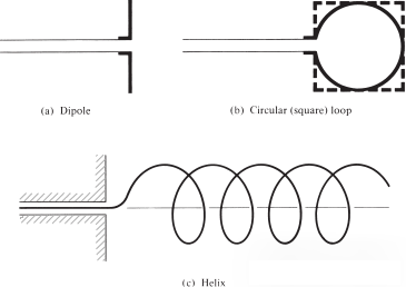
Figure 3
2. Aperture Antennas
Aperture antennas are playing a greater role due to the increasing demand for more complex forms of antennas and the utilization of higher frequencies. Some forms of aperture antennas (pyramidal, conical and rectangular horn antennas) are shown in Figure 4. This type of antenna is very useful for aircraft and spacecraft applications because they can be very conveniently mounted on the outer shell of the aircraft or spacecraft. In addition, they can be covered with a layer of dielectric material to protect them from harsh environments.

Figure 4
3. Microstrip antenna
Microstrip antennas became very popular in the 1970s, mainly for satellite applications. The antenna consists of a dielectric substrate and a metal patch. The metal patch can have many different shapes, and the rectangular patch antenna shown in Figure 5 is the most common. Microstrip antennas have a low profile, are suitable for planar and non-planar surfaces, are simple and inexpensive to manufacture, have high robustness when mounted on rigid surfaces, and are compatible with MMIC designs. They can be mounted on the surface of aircraft, spacecraft, satellites, missiles, cars, and even mobile devices and can be conformally designed.
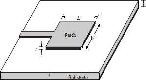
Figure 5
4. Array Antenna
The radiation characteristics required by many applications may not be achieved by a single antenna element. Antenna arrays can make the radiation from the elements synthesized to produce maximum radiation in one or more specific directions, a typical example is shown in Figure 6.
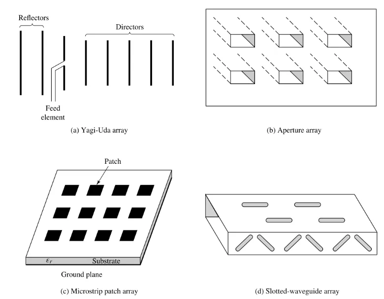
Figure 6
5. Reflector Antenna
The success of space exploration has also led to the rapid development of antenna theory. Due to the need for ultra-long-distance communication, extremely high-gain antennas must be used to transmit and receive signals millions of miles away. In this application, a common antenna form is the parabolic antenna shown in Figure 7. This type of antenna has a diameter of 305 meters or more, and such a large size is necessary to achieve the high gain required to transmit or receive signals millions of miles away. Another form of reflector is a corner reflector, as shown in Figure 7 (c).
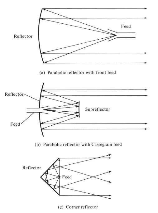
Figure 7
6. Lens Antennas
Lenses are primarily used to collimate incident scattered energy to prevent it from spreading in undesired radiation directions. By appropriately changing the geometry of the lens and choosing the right material, they can convert various forms of divergent energy into plane waves. They can be used in most applications like parabolic reflector antennas, especially at higher frequencies, and their size and weight become very large at lower frequencies. Lens antennas are classified according to their construction materials or geometric shapes, some of which are shown in Figure 8.
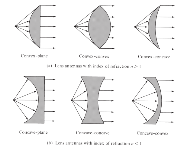
Figure 8
To learn more about antennas, please visit:
Post time: Jul-19-2024


