With the increasing popularity of wireless devices, data services have entered a new period of rapid development, also known as the explosive growth of data services. At present, a large number of applications are gradually migrating from computers to wireless devices such as mobile phones that are easy to carry and operate in real time, but this situation has also led to a rapid increase in data traffic and a shortage of bandwidth resources. According to statistics, the data rate on the market may reach Gbps or even Tbps in the next 10 to 15 years. At present, THz communication has reached a Gbps data rate, while the Tbps data rate is still in the early stages of development. A related paper lists the latest progress in Gbps data rates based on the THz band and predicts that Tbps can be obtained through polarization multiplexing. Therefore, to increase the data transmission rate, a feasible solution is to develop a new frequency band, which is the terahertz band, which is in the "blank area" between microwaves and infrared light. At the ITU World Radiocommunication Conference (WRC-19) in 2019, the frequency range of 275-450GHz has been used for fixed and land mobile services. It can be seen that terahertz wireless communication systems have attracted the attention of many researchers.
Terahertz electromagnetic waves are generally defined as the frequency band of 0.1-10THz (1THz=1012Hz) with a wavelength of 0.03-3 mm. According to the IEEE standard, terahertz waves are defined as 0.3-10THz. Figure 1 shows that the terahertz frequency band is between microwaves and infrared light.

Fig. 1 Schematic diagram of THz frequency band.
Development of Terahertz Antennas
Although terahertz research began in the 19th century, it was not studied as an independent field at that time. The research on terahertz radiation was mainly focused on the far-infrared band. It was not until the mid-to-late 20th century that researchers began to advance millimeter wave research to the terahertz band and conduct specialized terahertz technology research.
In the 1980s, the emergence of terahertz radiation sources made the application of terahertz waves in practical systems possible. Since the 21st century, wireless communication technology has developed rapidly, and people's demand for information and the increase in communication equipment have put forward more stringent requirements on the transmission rate of communication data. Therefore, one of the challenges of future communication technology is to operate at a high data rate of gigabits per second in one location. Under the current economic development, spectrum resources have become increasingly scarce. However, human requirements for communication capacity and speed are endless. For the problem of spectrum congestion, many companies use multiple-input multiple-output (MIMO) technology to improve spectrum efficiency and system capacity through spatial multiplexing. With the advancement of 5G networks, the data connection speed of each user will exceed Gbps, and the data traffic of base stations will also increase significantly. For traditional millimeter wave communication systems, microwave links will not be able to handle these huge data streams. In addition, due to the influence of line of sight, the transmission distance of infrared communication is short and the location of its communication equipment is fixed. Therefore, THz waves, which are between microwaves and infrared, can be used to build high-speed communication systems and increase data transmission rates by using THz links.
Terahertz waves can provide a wider communication bandwidth, and its frequency range is about 1000 times that of mobile communications. Therefore, using THz to build ultra-high-speed wireless communication systems is a promising solution to the challenge of high data rates, which has attracted the interest of many research teams and industries. In September 2017, the first THz wireless communication standard IEEE 802.15.3d-2017 was released, which defines point-to-point data exchange in the lower THz frequency range of 252-325 GHz. The alternative physical layer (PHY) of the link can achieve data rates of up to 100 Gbps at different bandwidths.
The first successful THz communication system of 0.12 THz was established in 2004, and the THz communication system of 0.3 THz was realized in 2013. Table 1 lists the research progress of terahertz communication systems in Japan from 2004 to 2013.
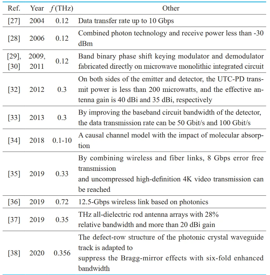
Table 1 Research progress of terahertz communication systems in Japan from 2004 to 2013
The antenna structure of a communication system developed in 2004 was described in detail by Nippon Telegraph and Telephone Corporation (NTT) in 2005. The antenna configuration was introduced in two cases, as shown in Figure 2.
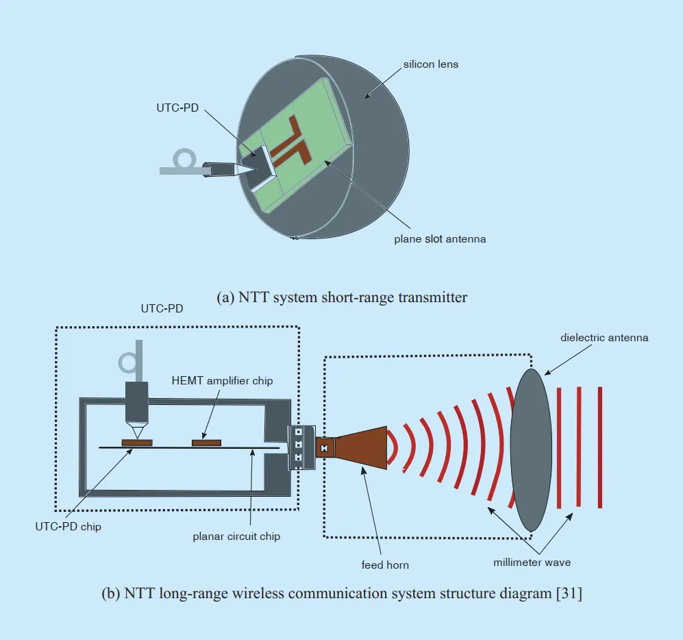
Figure 2 Schematic diagram of Japan’s NTT 120 GHz wireless communication system
The system integrates photoelectric conversion and antenna and adopts two working modes:
1. In a close-range indoor environment, the planar antenna transmitter used indoors consists of a single-line carrier photodiode (UTC-PD) chip, a planar slot antenna and a silicon lens, as shown in Figure 2(a).
2. In a long-range outdoor environment, in order to improve the influence of large transmission loss and low sensitivity of the detector, the transmitter antenna must have high gain. The existing terahertz antenna uses a Gaussian optical lens with a gain of more than 50 dBi. The feed horn and dielectric lens combination is shown in Figure 2(b).
In addition to developing a 0.12 THz communication system, NTT also developed a 0.3THz communication system in 2012. Through continuous optimization, the transmission rate can be as high as 100Gbps. As can be seen from Table 1, it has made a great contribution to the development of terahertz communication. However, the current research work has the disadvantages of low operating frequency, large size and high cost.
Most of the terahertz antennas currently used are modified from millimeter wave antennas, and there is little innovation in terahertz antennas. Therefore, in order to improve the performance of terahertz communication systems, an important task is to optimize terahertz antennas. Table 2 lists the research progress of German THz communication. Figure 3 (a) shows a representative THz wireless communication system combining photonics and electronics. Figure 3 (b) shows the wind tunnel test scene. Judging from the current research situation in Germany, its research and development also has disadvantages such as low operating frequency, high cost and low efficiency.
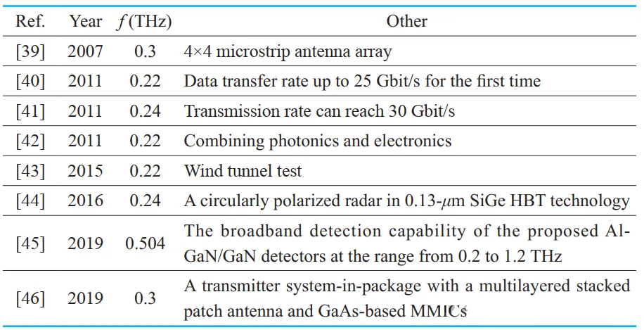
Table 2 Research progress of THz communication in Germany
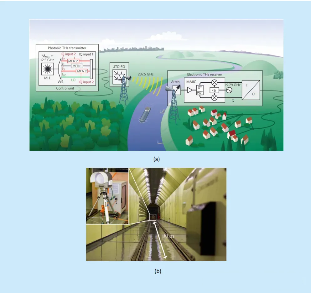
Figure 3 Wind tunnel test scene
The CSIRO ICT Center has also initiated research on THz indoor wireless communication systems. The center studied the relationship between the year and the communication frequency, as shown in Figure 4. As can be seen from Figure 4, by 2020, research on wireless communications tends to the THz band. The maximum communication frequency using the radio spectrum increases about ten times every twenty years. The center has made recommendations on the requirements for THz antennas and proposed traditional antennas such as horns and lenses for THz communication systems. As shown in Figure 5, two horn antennas work at 0.84THz and 1.7THz respectively, with a simple structure and good Gaussian beam performance.
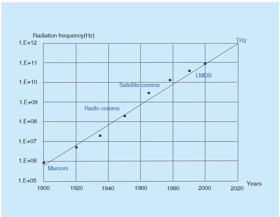
Figure 4 Relationship between year and frequency
Figure 5 Two types of horn antennas
The United States has conducted extensive research on the emission and detection of terahertz waves. Famous terahertz research laboratories include the Jet Propulsion Laboratory (JPL), the Stanford Linear Accelerator Center (SLAC), the US National Laboratory (LLNL), the National Aeronautics and Space Administration (NASA), the National Science Foundation (NSF), etc. New terahertz antennas for terahertz applications have been designed, such as bowtie antennas and frequency beam steering antennas. According to the development of terahertz antennas, we can get three basic design ideas for terahertz antennas at present, as shown in Figure 6.
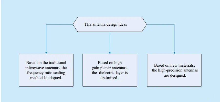
Figure 6 Three basic design ideas for terahertz antennas
The above analysis shows that although many countries have paid great attention to terahertz antennas, it is still in the initial exploration and development stage. Due to high propagation loss and molecular absorption, THz antennas are usually limited by transmission distance and coverage. Some studies focus on lower operating frequencies in the THz band. Existing terahertz antenna research mainly focuses on improving gain by using dielectric lens antennas, etc., and improving communication efficiency by using appropriate algorithms. In addition, how to improve the efficiency of terahertz antenna packaging is also a very urgent issue.
General THz antennas
There are many types of THz antennas available: dipole antennas with conical cavities, corner reflector arrays, bowtie dipoles, dielectric lens planar antennas, photoconductive antennas for generating THz source radiation sources, horn antennas, THz antennas based on graphene materials, etc. According to the materials used to make THz antennas, they can be roughly divided into metal antennas (mainly horn antennas), dielectric antennas (lens antennas), and new material antennas. This section first gives a preliminary analysis of these antennas, and then in the next section, five typical THz antennas are introduced in detail and analyzed in depth.
1. Metal antennas
The horn antenna is a typical metal antenna that is designed to work in the THz band. The antenna of a classic millimeter wave receiver is a conical horn. Corrugated and dual-mode antennas have many advantages, including rotationally symmetric radiation patterns, high gain of 20 to 30 dBi and low cross-polarization level of -30 dB, and coupling efficiency of 97% to 98%. The available bandwidths of the two horn antennas are 30%-40% and 6%-8%, respectively.
Since the frequency of terahertz waves is very high, the size of the horn antenna is very small, which makes the processing of the horn very difficult, especially in the design of antenna arrays, and the complexity of the processing technology leads to excessive cost and limited production. Due to the difficulty in manufacturing the bottom of the complex horn design, a simple horn antenna in the form of a conical or conical horn is usually used, which can reduce the cost and process complexity, and the radiation performance of the antenna can be maintained well.
Another metal antenna is a traveling wave pyramid antenna, which consists of a traveling wave antenna integrated on a 1.2 micron dielectric film and suspended in a longitudinal cavity etched on a silicon wafer, as shown in Figure 7. This antenna is an open structure that is compatible with Schottky diodes. Due to its relatively simple structure and low manufacturing requirements, it can generally be used in frequency bands above 0.6 THz. However, the sidelobe level and cross-polarization level of the antenna are high, probably due to its open structure. Therefore, its coupling efficiency is relatively low (about 50%).

Figure 7 Traveling wave pyramidal antenna
2. Dielectric antenna
The dielectric antenna is a combination of a dielectric substrate and an antenna radiator. Through proper design, the dielectric antenna can achieve impedance matching with the detector, and has the advantages of simple process, easy integration, and low cost. In recent years, researchers have designed several narrowband and broadband side-fire antennas that can match the low-impedance detectors of terahertz dielectric antennas: butterfly antenna, double U-shaped antenna, log-periodic antenna, and log-periodic sinusoidal antenna, as shown in Figure 8. In addition, more complex antenna geometries can be designed through genetic algorithms.
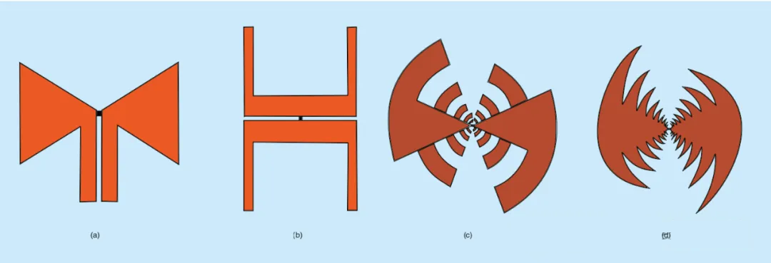
Figure 8 Four types of planar antennas
However, since the dielectric antenna is combined with a dielectric substrate, a surface wave effect will occur when the frequency tends to the THz band. This fatal disadvantage will cause the antenna to lose a lot of energy during operation and lead to a significant reduction in the antenna radiation efficiency. As shown in Figure 9, when the antenna radiation angle is greater than the cutoff angle, its energy is confined in the dielectric substrate and coupled with the substrate mode.
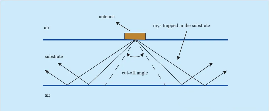
Figure 9 Antenna surface wave effect
As the thickness of the substrate increases, the number of high-order modes increases, and the coupling between the antenna and the substrate increases, resulting in energy loss. In order to weaken the surface wave effect, there are three optimization schemes:
1) Load a lens on the antenna to increase the gain by using the beamforming characteristics of electromagnetic waves.
2) Reduce the thickness of the substrate to suppress the generation of high-order modes of electromagnetic waves.
3) Replace the substrate dielectric material with an electromagnetic band gap (EBG). The spatial filtering characteristics of EBG can suppress high-order modes.
3. New material antennas
In addition to the above two antennas, there is also a terahertz antenna made of new materials. For example, in 2006, Jin Hao et al. proposed a carbon nanotube dipole antenna. As shown in Figure 10 (a), the dipole is made of carbon nanotubes instead of metal materials. He carefully studied the infrared and optical properties of the carbon nanotube dipole antenna and discussed the general characteristics of the finite-length carbon nanotube dipole antenna, such as input impedance, current distribution, gain, efficiency and radiation pattern. Figure 10 (b) shows the relationship between the input impedance and frequency of the carbon nanotube dipole antenna. As can be seen in Figure 10(b), the imaginary part of the input impedance has multiple zeros at higher frequencies. This indicates that the antenna can achieve multiple resonances at different frequencies. Obviously, the carbon nanotube antenna exhibits resonance within a certain frequency range (lower THz frequencies), but is completely unable to resonate outside this range.
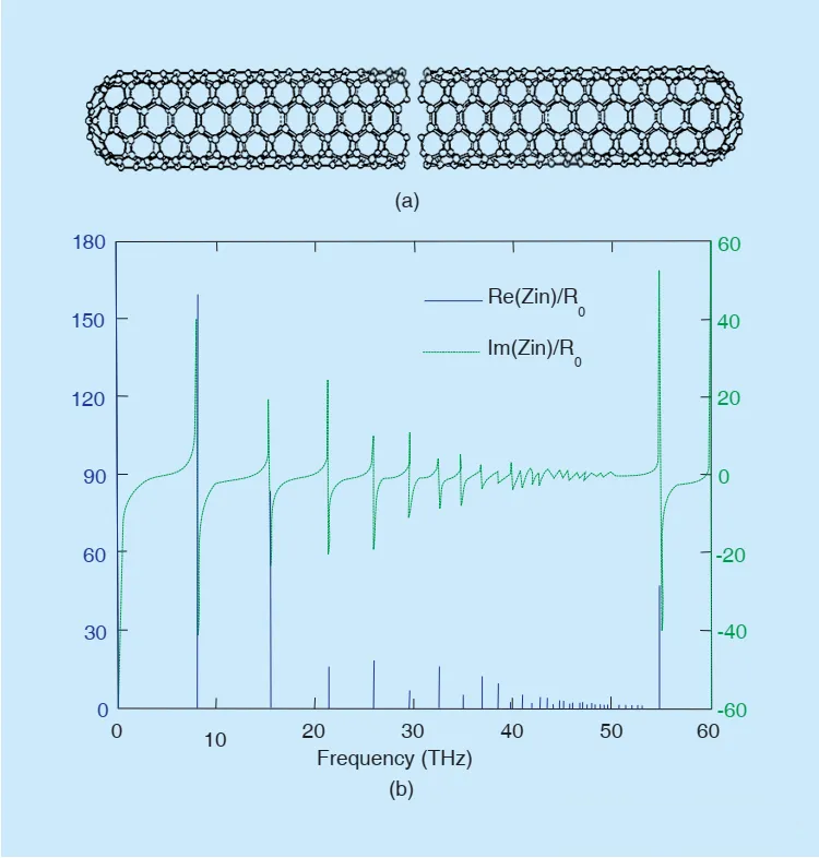
Figure 10 (a) Carbon nanotube dipole antenna. (b) Input impedance-frequency curve
In 2012, Samir F. Mahmoud and Ayed R. AlAjmi proposed a new terahertz antenna structure based on carbon nanotubes, which consists of a bundle of carbon nanotubes wrapped in two dielectric layers. The inner dielectric layer is a dielectric foam layer, and the outer dielectric layer is a metamaterial layer. The specific structure is shown in Figure 11. Through testing, the radiation performance of the antenna has been improved compared with single-walled carbon nanotubes.
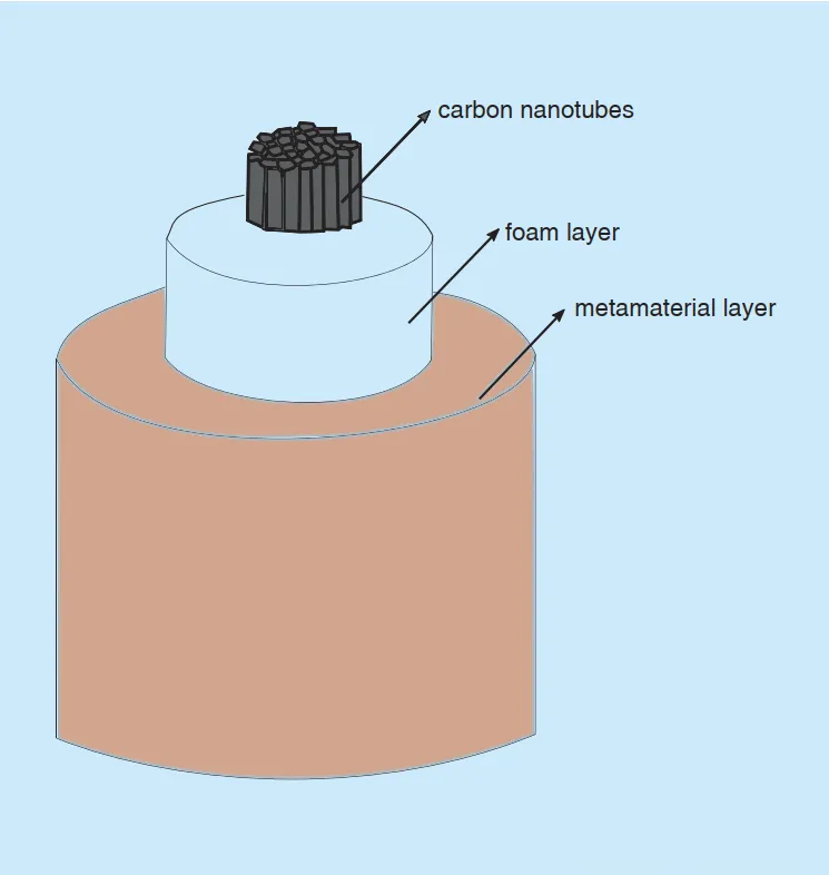
Figure 11 New terahertz antenna based on carbon nanotubes
The new material terahertz antennas proposed above are mainly three-dimensional. In order to improve the bandwidth of the antenna and make conformal antennas, planar graphene antennas have received widespread attention. Graphene has excellent dynamic continuous control characteristics and can generate surface plasma by adjusting the bias voltage. Surface plasma exists on the interface between positive dielectric constant substrates (such as Si, SiO2, etc.) and negative dielectric constant substrates (such as precious metals, graphene, etc.). There are a large number of "free electrons" in conductors such as precious metals and graphene. These free electrons are also called plasmas. Due to the inherent potential field in the conductor, these plasmas are in a stable state and are not disturbed by the outside world. When the incident electromagnetic wave energy is coupled to these plasmas, the plasmas will deviate from the steady state and vibrate. After the conversion, the electromagnetic mode forms a transverse magnetic wave at the interface. According to the description of the dispersion relation of metal surface plasma by the Drude model, metals cannot naturally couple with electromagnetic waves in free space and convert energy. It is necessary to use other materials to excite surface plasma waves. Surface plasma waves decay rapidly in the parallel direction of the metal-substrate interface. When the metal conductor conducts in the direction perpendicular to the surface, a skin effect occurs. Obviously, due to the small size of the antenna, there is a skin effect in the high frequency band, which causes the antenna performance to drop sharply and cannot meet the requirements of terahertz antennas. The surface plasmon of graphene not only has higher binding force and lower loss, but also supports continuous electrical tuning. In addition, graphene has complex conductivity in the terahertz band. Therefore, slow wave propagation is related to the plasma mode at terahertz frequencies. These characteristics fully demonstrate the feasibility of graphene to replace metal materials in the terahertz band.
Based on the polarization behavior of graphene surface plasmons, Figure 12 shows a new type of strip antenna, and proposes the band shape of the propagation characteristics of plasma waves in graphene. The design of tunable antenna band provides a new way to study the propagation characteristics of new material terahertz antennas.
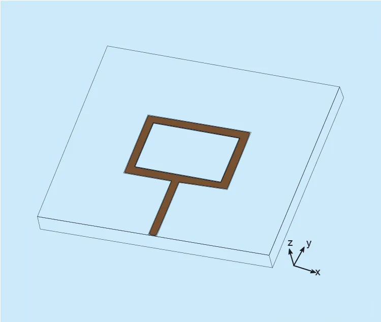
Figure 12 New strip antenna
In addition to exploring unit new material terahertz antenna elements, graphene nanopatch terahertz antennas can also be designed as arrays to build terahertz multi-input multi-output antenna communication systems. The antenna structure is shown in Figure 13. Based on the unique properties of graphene nanopatch antennas, the antenna elements have micron-scale dimensions. Chemical vapor deposition directly synthesizes different graphene images on a thin nickel layer and transfers them to any substrate. By selecting an appropriate number of components and changing the electrostatic bias voltage, the radiation direction can be effectively changed, making the system reconfigurable.
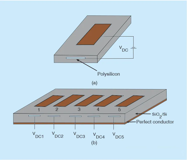
Figure 13 Graphene nanopatch terahertz antenna array
The research of new materials is a relatively new direction. The innovation of materials is expected to break through the limitations of traditional antennas and develop a variety of new antennas, such as reconfigurable metamaterials, two-dimensional (2D) materials, etc. However, this type of antenna mainly depends on the innovation of new materials and the advancement of process technology. In any case, the development of terahertz antennas requires innovative materials, precise processing technology and novel design structures to meet the high gain, low cost and wide bandwidth requirements of terahertz antennas.
The following introduces the basic principles of three types of terahertz antennas: metal antennas, dielectric antennas and new material antennas, and analyzes their differences and advantages and disadvantages.
1. Metal antenna: The geometry is simple, easy to process, relatively low cost, and low requirements for substrate materials. However, metal antennas use a mechanical method to adjust the position of the antenna, which is prone to errors. If the adjustment is not correct, the performance of the antenna will be greatly reduced. Although the metal antenna is small in size, it is difficult to assemble with a planar circuit.
2. Dielectric antenna: The dielectric antenna has a low input impedance, is easy to match with a low impedance detector, and is relatively simple to connect with a planar circuit. The geometric shapes of dielectric antennas include butterfly shape, double U shape, conventional logarithmic shape and logarithmic periodic sine shape. However, dielectric antennas also have a fatal flaw, namely the surface wave effect caused by the thick substrate. The solution is to load a lens and replace the dielectric substrate with an EBG structure. Both solutions require innovation and continuous improvement of process technology and materials, but their excellent performance (such as omnidirectionality and surface wave suppression) can provide new ideas for the research of terahertz antennas.
3. New material antennas: At present, new dipole antennas made of carbon nanotubes and new antenna structures made of metamaterials have appeared. New materials can bring new performance breakthroughs, but the premise is the innovation of materials science. At present, the research on new material antennas is still in the exploratory stage, and many key technologies are not mature enough.
In summary, different types of terahertz antennas can be selected according to design requirements:
1) If simple design and low production cost are required, metal antennas can be selected.
2) If high integration and low input impedance are required, dielectric antennas can be selected.
3) If a breakthrough in performance is required, new material antennas can be selected.
The above designs can also be adjusted according to specific requirements. For example, two types of antennas can be combined to gain more advantages, but the assembly method and design technology must meet more stringent requirements.
To learn more about antennas, please visit:
Post time: Aug-02-2024


